|
53 CNC SYSTEM 2007.9/30 |
|
| 1.The following is a block diagram of my CNC system. It took about one year to complete the CNC addition through a trial and error process. |
|
 |
|
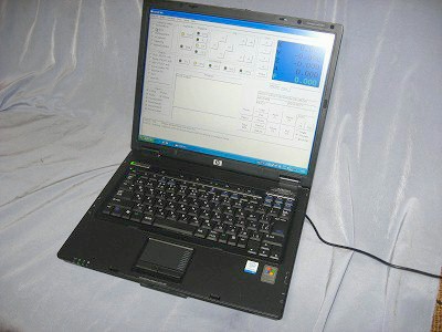 |
2.HP nx6120 It has a parallel connector and a USB interface. |
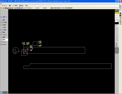 |
3.This is screen shot of CAD/CAM software. It is called "Nc Editor WT3NC." (Japanese Version only.) |
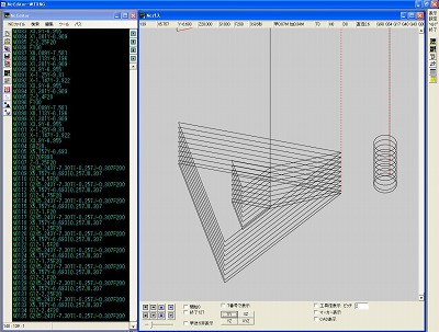 |
4.This is a screen shot of the CAM output. |
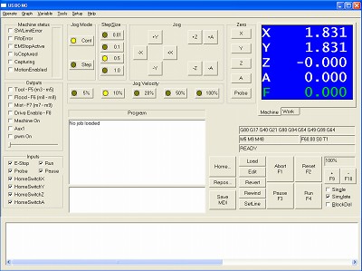 |
5. 5. This is a screen shot of the USB CNC control software that I mainly
use. This software has an intuitive interface and is easy to program. USB CNC SITE IS HERE |
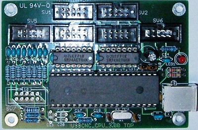 |
6. The USB CNC requires dedicated hardware that is supplied
by the developer. The step pulse is output from this board. |
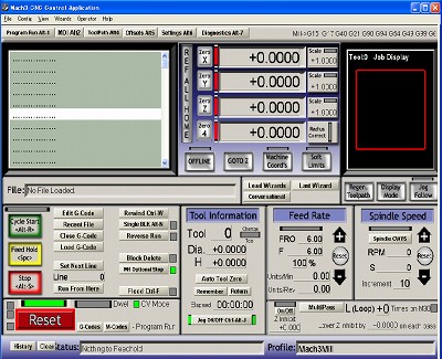 |
7. I also use the MACH as a subsystem. The step pulses are an output from the parallel port of the computer. |
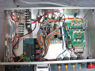 |
8.This is the inside of the control box. The control box includes the following boards: USB CNC Pulse Width Converter Level Convert Interface |
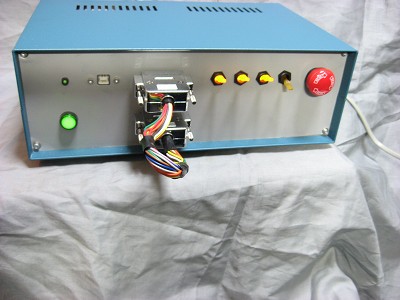 |
9. This is the front panel of the control box. The parallel connector is for the MACH. The Emergency STOP button is on the right side. A Power On indicator and Servo ON-OFF switches with LED are also included. |
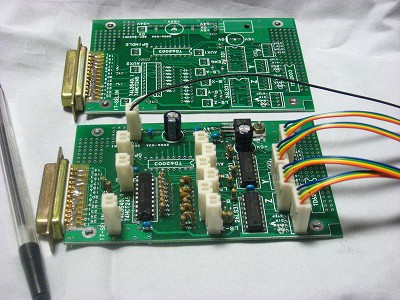 |
10. Level Convert Interface board. The output is 5 volts, balanced. This board was designed and produced by my friend. |
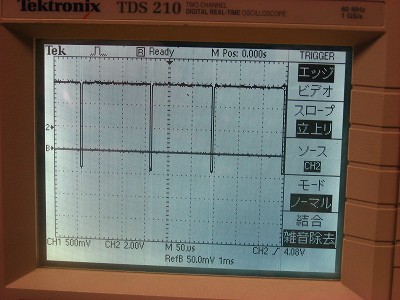 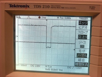 |
11. The output pulse is very narrow and can be varied. |
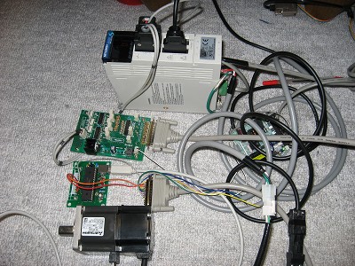 |
12. A trial run of the servo motor is shown. |
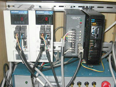 |
10.These are the motor driver amplifiers. The left two are servo motor amplifiers MITSUBISHI MR-J2S-40A The middle one is a stepping motor amplifier ORIENTAL MOTOR RKD5114L-A The right one is a stepping motor for the A axis. |
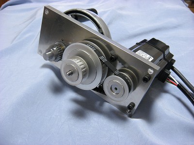 |
11. This is an interior view of the reduction gear mechanism. A manual handle is installed, but a clutch is included for handle movement to be OFF during CNC operations. The reduction mechanism is not always necessary. Direct couple system also works. |
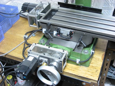 |
12.The mechanical limit switch is installed. The maximum feed speed is F2500. The movement of this system is very stable. Powerful, no stop, no step out. |
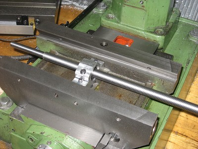 |
13. Ball screws are installed for the x-axis and y-axis. The ball screws greatly reduce the mechanical load of the servo motors. To me, the use of ball screws is needed to have reliable operation if a general purpose milling machine is converted to CNC. |
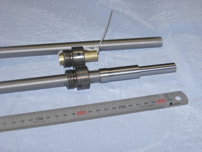 |
14.Ball screws and nuts. One end has been processed. |
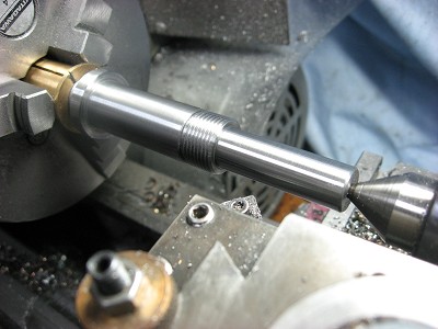 |
15.The end of the ball is being machined. The ball screws are hardened
and require specialized machining techniques to produce the needed precision.
|
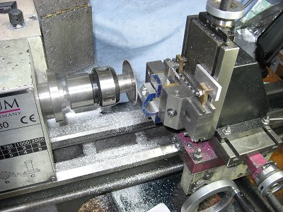 |
16.Making a ball screw nut holder with the lathe because the milling machine is disassembled. |
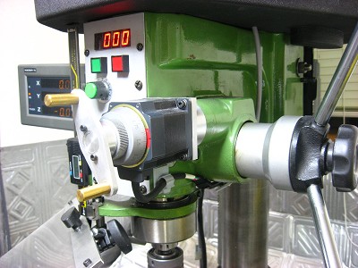 |
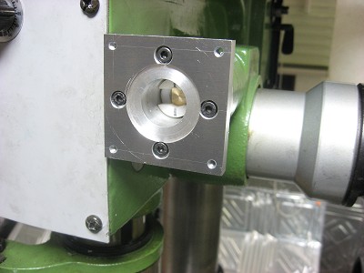
17. This is Z-Axis view. A stepper motor is installed on the micro movement mechanism. |
 |
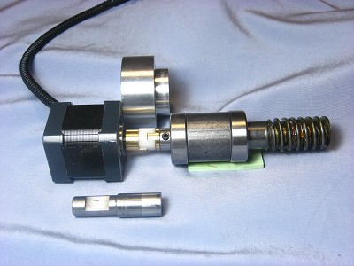
18.Inside view of the Z-Axis. |
 |
19.This is a view of the z-axis mechanism. A small, shop made oldham type coupling is used. |
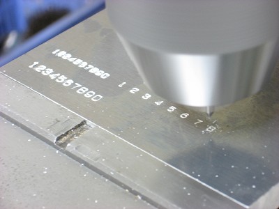 |
20.One of the most impressive applications of the CNC system. |
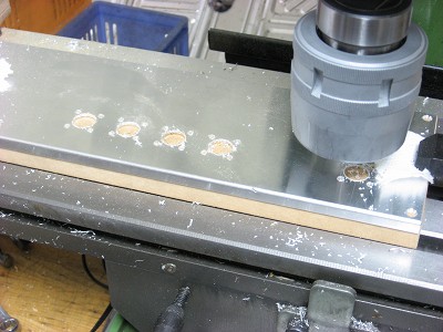 |
21.The rear panel holes of the control box were made with the CNC. PLEASE SEE THE MOVIE FILE |
| The following is a CNC system in the stepping motor before the current servo system is completed. | |
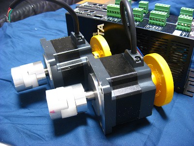 |
22.Stepping motors and drivers. |
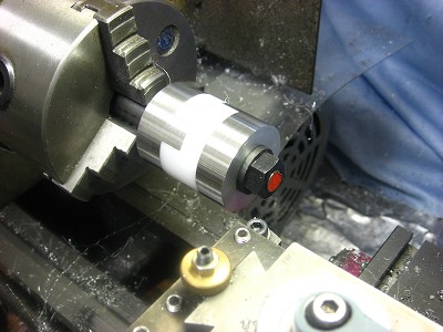 |
23.Finishing of the oldham type coupling. |
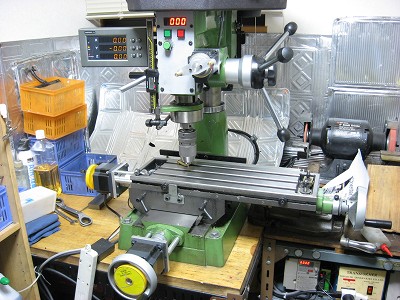 |
24.This is my first CNC system. It consists of stepper motors and a direct
drive system. Stepper motors are much cheaper than servo motors and easier to control. I am pleased to report that the CNC system works very well. |
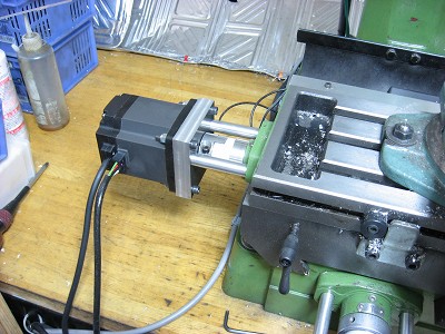 |
25.This is a view during testing of the stepper motor while it provides direct drive to the x-axis. |