 |
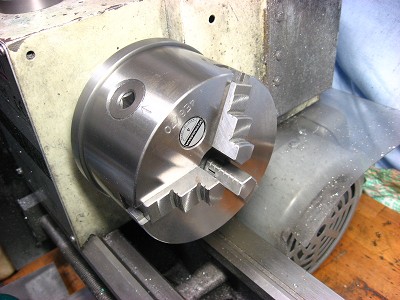
1. I recently purchased a new chuck for my lathe which needed an adapter
plate.
|
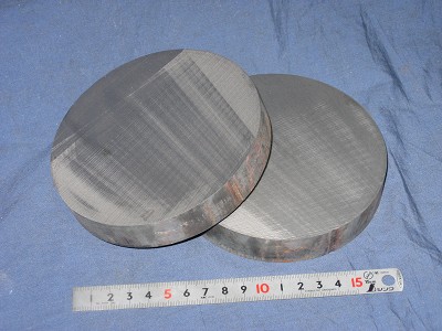 |
2. The material for the adapter plate is cast iron, and the diameter is
130 mm.
Two pieces were prepared, but only one will be used if all goes well. |
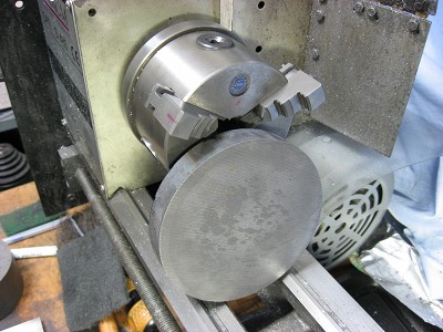 |
3. Material is too big for gripping in my lathe chuck, so it will be machined
while directly bolted to the lathe's spindle flange. |
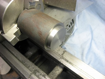 |
4. A cast iron "gage" is machined that will be used to check
the machining of the side of the adapter that faces the lathe spindle.
Both size and taper will be checked.
|
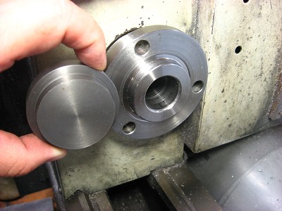 |
5. The completed gage.
|
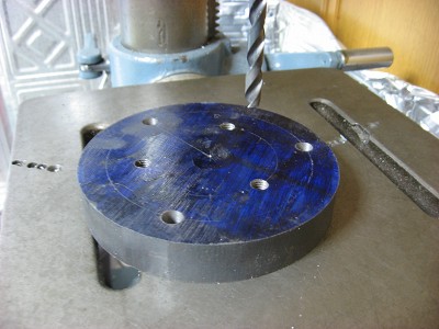 |
6. Holes are layed out, drilled and tapped in the adapter plate. |
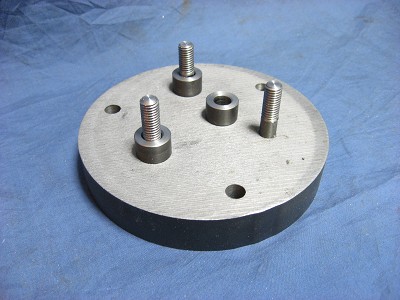 |
7. Threaded studs, produced beforehand, are threaded into the adapter
plate.
Three identical standoffs are used to offset the adapter plate from the
lathe spindle.
|
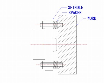 |
7-1 The setting is made as shown in the left figure. |
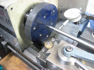 |
8. Centering the adapter plate on the lathe spindle, prior to securing
the nuts.
|
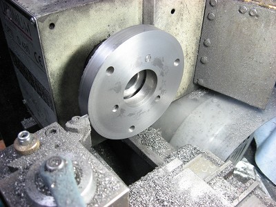 |
9. A hole is bored in the adaptor plate to match the lathe spindle
flange. The gage is used to assure an accurate fit. |
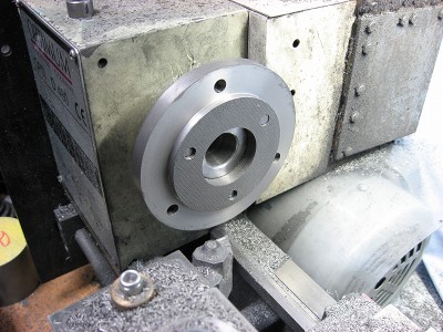 |
10. After the adapter plate and threaded studs are reversed, a shoulder
is machined to match the size of the new chuck.
|
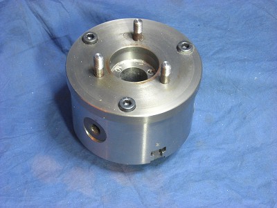 |
11. The adapter plate is bolted to the new chuck.
The project is complete.
|
|
|
 |
|