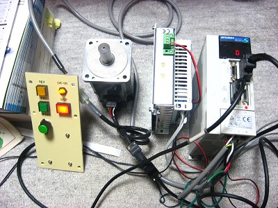
Changing milling machine spindle motor. This change replaces the original equipment motor with a much smaller servo motor. The original equipment motor was powered by a three-phase inverter. Replacing the original equipment motor provides more room in my narrow workshop and also improves performance. Equipment 1. Motor HC-KFS73 MITSUBISHI 2. Servo control unit MR-J2S-70A MITSUBISHI 3. 5V power supply unit for the front panel digital circuit Design concept 1. Add servo motor to right side of milling machine to reduce back space as much as possible. 2. The servo motor is rated at 750W, the same as the original equipment motor. 3. To save time the original main spindle pulley was retained even though there was a desire to reduce its size. 4.It was thought that maximum speed of the main spindle secured 2000 rpm or more. The diameter of the servo motor pulley is 105 mm, resulting in a maximum main spindle speed of about 2,700 rpm. (4000 rpm in maximum speed of the motor time). 5. With the belt positioned on the smaller servo motor pulley the maximum main spindle speed is about 2,000 rpm, and torque is increased. 6. A FWD/REV switch has been included on the control panel for such operations as tapping. 7. A servo motor OFF switch has been included on the control panel to allow free rotation of the spindle during such operations as tool interchange. 8. The control panel is located for ready operator access. ======================== Impression 1. A compact milling machine was achieved by replacing the original equipment motor with a smaller servo motor. 2. The servo motor provides for super low speed operation, very effective for tapping and chamfering. 3. The servo motor generated much less electromagnetic interference than the three-phase inverter. The DROs no longer malfunctioned. |
1. Test run of the new servo motor. | |
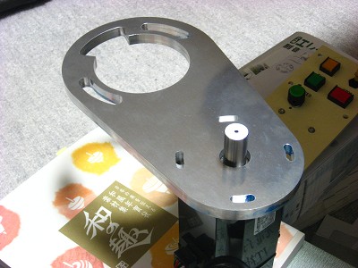
2. Bracket for motor mounting. The material is hard aluminum, 12 mm thick.
The angle of the bracket and servo motor can both be adjusted. |
|
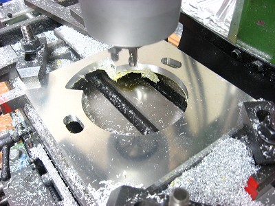
3. Machining the spacer. Movie of milling process The spacer is mounted under the motor mounting bracket, but it is difficult to see in the photographs. |
|
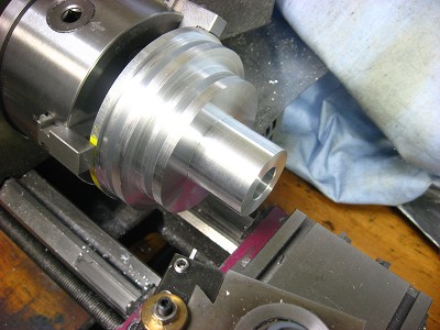
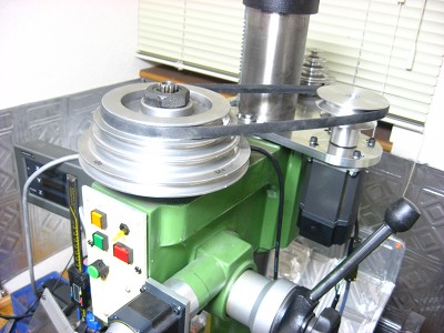
4. Machining the servo motor pulley. The larger pulley has a diameter of 105 mm. |
|
5. All parts are assembled. The original safety cover was removed. |
|
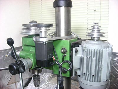
6. Size of servo motor compared with original equipment three-phase motor. The motor on the back side is a three-phase motor of 1.5Kw driven with the inverter. The difference between the size of the servo motor and an original motor can be seen. |
|
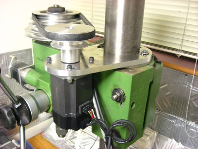
7. The 3-phase motor has been removed. The motor position is designed so that the fixed screw of the column can be turned. |
|
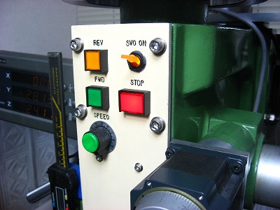
8. The servo motor control panel is mounted on the front of the mill head. Forward, reverse, stop, servo-on switches and speed control volume are on the panel. |
|
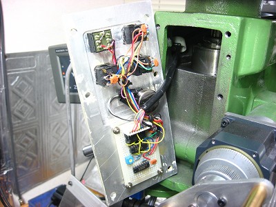
9. A back view of the control panel. It has a small digital circuit for sending the motor on-off signal to the servo control unit. |
|
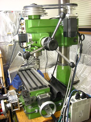
10. Completed I am very satisfied with the result. |
|
|
|