|
62. CNC MACHINE 2009/4/23 |
|
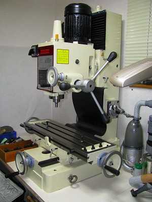 |
1. Base Machine It is necessary to secure the accuracy of the table, the inclination of the main axis, and the accuracy such as swinging of the main axis as a mechanical performance though it doesn't limit to the CNC machine. The machine for the hobby is different from an industrial machine, and most manufacturers are not guaranteeing accuracy. Therefore, accuracy is depending on luck. When the accuracy of my machine's had been confirmed, it was a practicable value. Especially, the accuracy of the inclination of Y axis is important because the adjustment is impossible near in fact. Moreover, the smoothness of the movement of the table is also important though it is an element different from accuracy. It meets those requirements, and I think the machine to be an appropriate level as the base machine. |
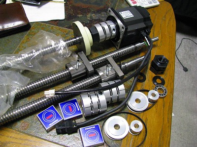 |
2. Ball Screws The diameter of an original trapezoid screw is 25mm. Therefore, the ball screw wanted also to adopt the one of 25mm. However, the ball screw holder might be too large, and it be not attachable. Therefore, the ball screw was selected from the size of the holder that was able to be installed. In the screw with high accuracy, where it can be allowed is a problem because the price is high. Because the ball screws were important parts, I carefully selected it. |
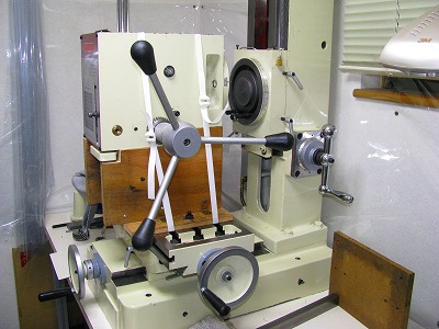 |
3.To install the ball screw in Z axis, the head unit is removed. The head unit puts on a wooden stand, and removes the head by the table movement. |
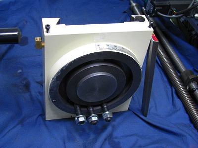 |
4.The base where the head unit is installed is detached. |
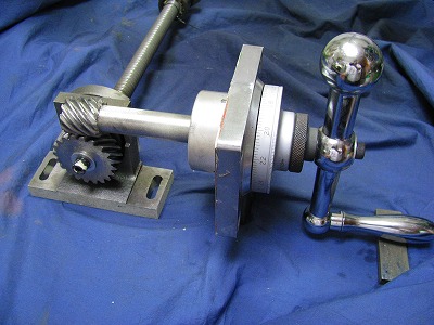 |
5.It is a structure of Z axis. The manual handle is connected with the screw with the gear mechanism. |
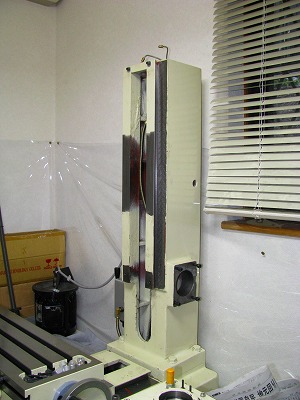 |
6.All of Z axis mechanism were removed. |
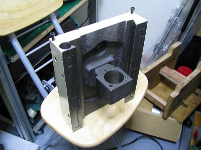 |
7.Z axis base and the attaching portion of the holder for a trapezoid screw
have combined. The screw hole for the ball screw installation is newly processed. |
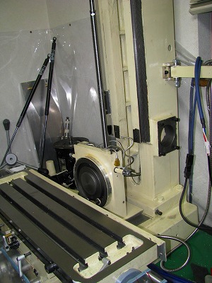 |
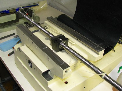
8. The ball screw is assembled, and installed. |
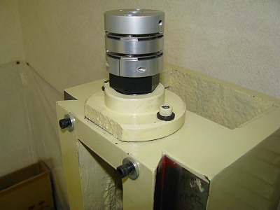 |
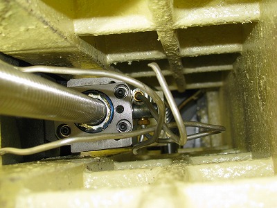
9. The ball screw is fixed in the upper part. The coupling was installed. |
 |
10. The installation of Z axis is seen from the upper part. |
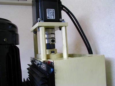 |
11. The motor of Z axis was installed. |
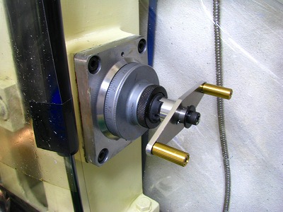 |
12. It is a manual handle of Z axis. The clutch mechanism was applied. |
 |
13. When the ball screw of the XY axis is installed, the size putting out
from the article is necessary. Therefore, the original size drawing was written and the installation position of the ball screw was decided. The XY axis adopted the ball screw of as big an axis diameter as possible. The size of the ball screw was selected beforehand by the installation space measurement. |
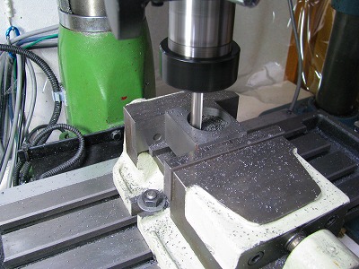 |
14. The ball screw holder is produced. |
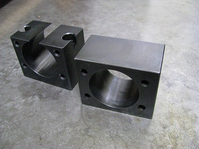 |
15. Thes are ball screw holder for X and Y axis. |
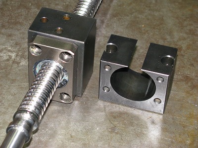 |
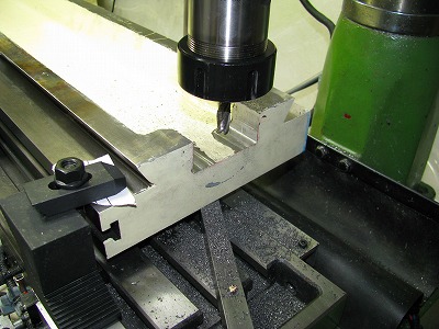
16. The ball screw is installed in the holder. |
 |
17. The nut of the ball screw is larger than the nut holder of an original
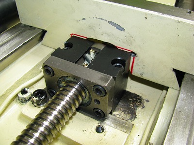
trapezoid screw. Therefore, the nut obstructs after assembly and the table cannot be assembled. Therefore, it installed it by shaving off a part of the table. The part that has been shaved off is necessary as the ball screw fixed portion. Therefore, parts are produced, it makes to the structure like the cap separately, and it buries it. |
 |
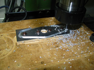
18. The table can be installed not caught to the ball screw nut. |
 |
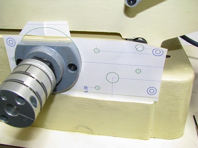
19. Making a manual handle. |
 |
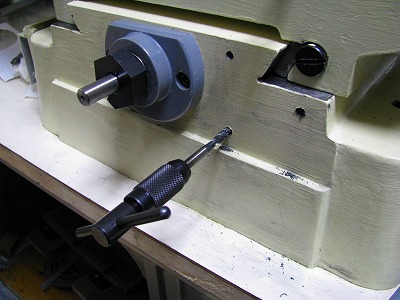
20. It prepares it. print the drawing by the original size to install a fixed plate for Y axis, strike the punch by the article match, and process the screw hole to the main body |
 |
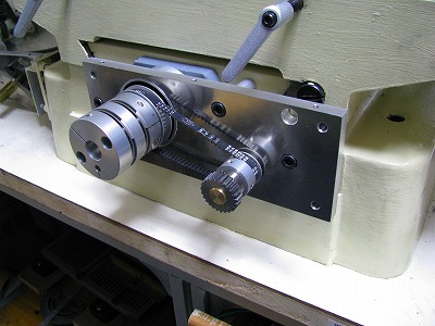
21. Tapping hole is making. |
 |
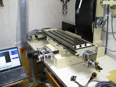
22. To minimize the backlash, transportation unites between the motor and
the ball screw directly with the coupling without the deceleration mechanism.
The problem of a direct connection is whether the ball screw be able to be driven enough in the servo motor and it is powerful. There is thrust of 100Kg or more when this respect is measured even if the driving performance of Z axis adjusts the jib hard. Therefore, I think that it is a result that a drive enough by 400W motor is possible even if the deceleration mechanism is not installed. Moreover, a manual handle is installed in the XYZ axis and it designs so that the manual may cut. A manual handle is made to install the clutch mechanism, and to be able to separate the steering wheel when NC operates. |
 |
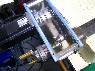
23. All drive mechanism is installed. |
 |
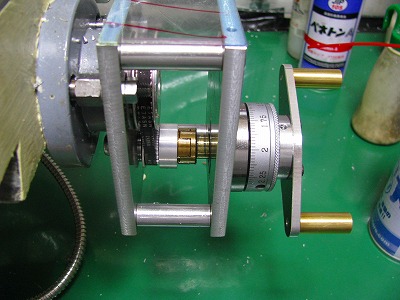
24. This is a Y axis driving mechanism. |
 |
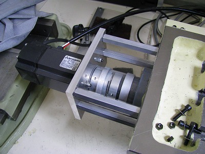
25. This is X axis manual handle mechansm. A cluch mecahanism is also attached. |
 |
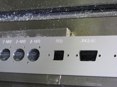
26. The motor for X axis. |
 |
27. This is a hole processing and a character processing of the control panel. |
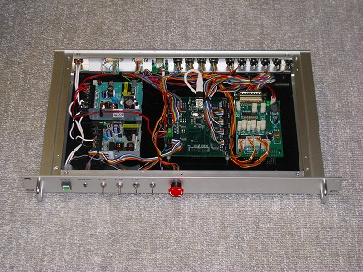 |
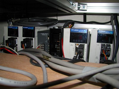
28. The electrical circuit was put in 1U rack of the EIA standard. The lean space can be effectively used. USB-CNCV4 is adopted in the control. The interface of the balance output is put in the connection with the servo amplifier. As for a front panel, power switch, monitor LED of the CNC substrate, servo ON/OFF switch, and the emergency stop switch are arranged. |
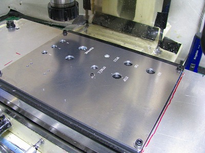 |
29. Making the front panel of the machine. |
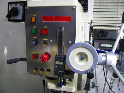 |
30. The panel has a digital read out for quill. |
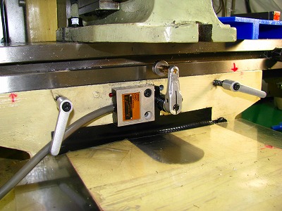 |
31. A limit switch for X axis. |
 |
32.
Resolution per pulse is revokable in the internal parameter setting in the combination of this servo amplifier and the motor. In this setting, it was set that it became the distance of 0.001mm by one input pulse. |