 |
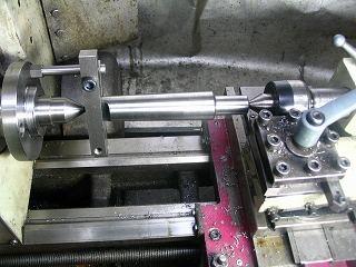
1. (Taper arbour)
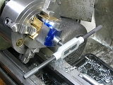
Setup to machining for purchased MT3/JT6 arbor.
The Jacob's section has been machined flat. |
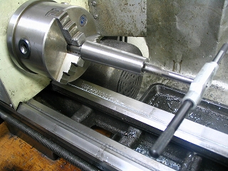 |
2. The tang has been removed and the flat section from the Jacob's
taper is held in the chuck for drilling and tapping the 12 mm draw-bar
thread. |
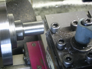 |
3. (Taper arbour)
Arbor secured in lathe spindle with draw-bar, ready for machining
to 12mm diameter.
|
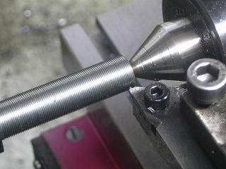 |
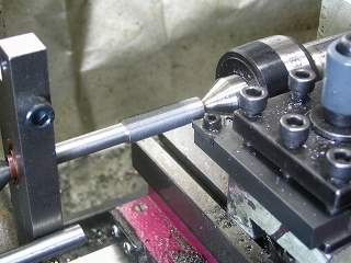
4. Micrometer shaft threaded -- diameter 10 mm, pitch 0.5 mm. Material
is free-cutting steel. |
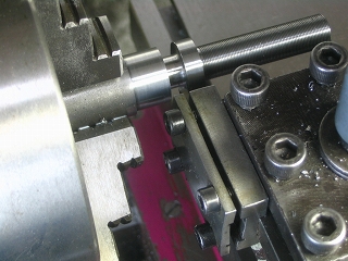 |
5. Machining micrometer shaft. |
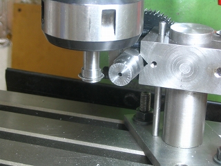 |
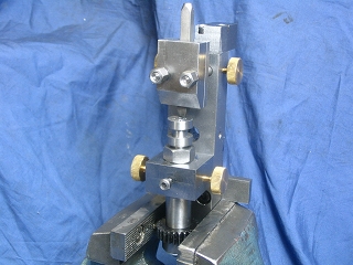
6. Engraving micrometer scale lines with 0.1 mm slitting saw, depth of
0.1 mm.
See Article Number 48 for making a small slitting saw arbor.
See Article Number 15 for the design of the Simple Index Stand. |
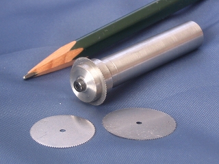 |
7. Slitting saws and arbor. The best thickness for a scale line is
in the order of 0.2 mm. |
 |
8. Punching numbers on the face of the micrometer using a punch mark holder.
See Article Number 14 for making a Punch Mark Holder.
|
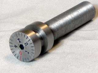 |
9. Engraved lines have been filled with a marker pen to improve contrast.
Note that the micrometer dial has 25 divisions and the micrometer thread
has a 0.5 mm pitch. Thus, a complete turn of the dial moves the boring
head 0.5 mm, and adjusting the dial one increment moves the boring head
0.5/25 = 0.02 mm.
An Allen head set-screw is fixed in the center of the micrometer head with
Loctite, medium strength. An Allen key can then be used to adjust
the boring head.
|
 |
10. Making a custom-sized, metric tap, 10 mm x 0.5 mm for the internal
thread of the micrometer.
Material is carbon steel. (0.45% carbon steel)
|
 |
11. Cutting flutes while special tap is held in Simple Index Stand.
After cutting flutes the relief angles are ground or filed.
|
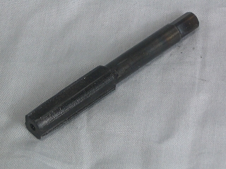 |
12. The special tap, machined, heat treated, and ready for use.
|
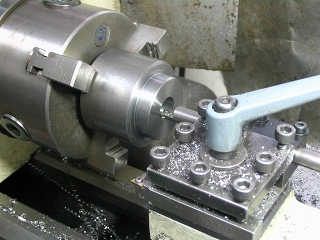 |
13. (Body)
The body is made from 55mm round free-cutting steel. |
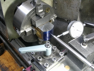 |
14. Body centered in chuck using the setup shown.
Bore a 17.2 mm hole for the micrometer dial head, followed by finishing
the rest of the hole to 9.5 mm.
Thread the 9.5 mm hole with the custom tap. (See #12.)
|
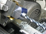  |
14.5 A temporary sleeve guides the custom tap.
The sleeve has a 17.2 mm OD and 9.5 mm ID. |
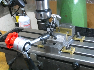 |
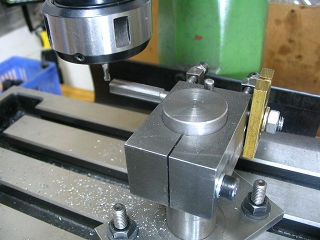
15. Taking care to align vise to milling table, as next steps require precise
parallel cuts. |
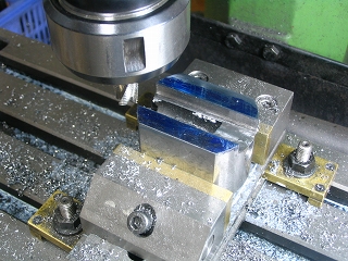 |
16. (Body)
Slotting prior to cutting dovetail.
Depth of cut is 8 mm using a 12 mm roughing end mill.
|
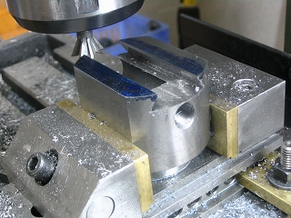 |
17. Completed dovetails, to be followed by honing with an oil stone.
|
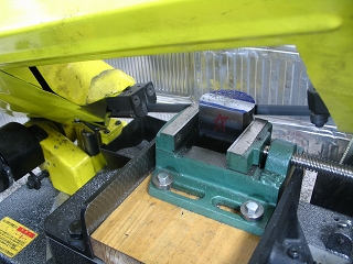 |
18. Cutting away unnecessary parts of the sub-head, leaving allowance for
finish milling. |
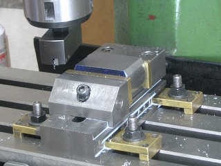 |
19. Sub-head surfaced with fly-cutter, using slow feed to produce
a fine finish. |
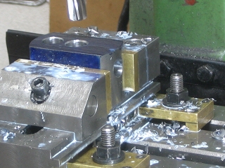 |
20. Drill sub-head holes and ream to 12 mm for a exactly size of boring bar shanks.
|
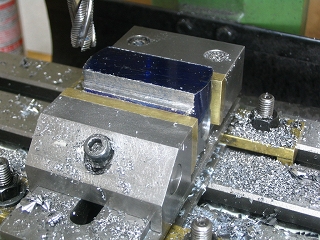 |
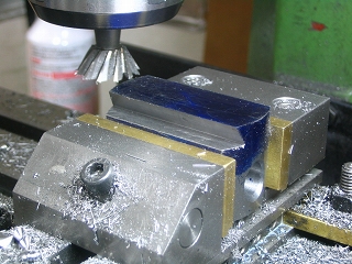
21. (Sub Body)
Preparing sub-head for dovetails using roughing end mill.
|
 |
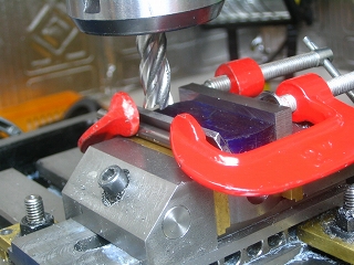
22. (Sub Body)
Dovetails finished. |
 |
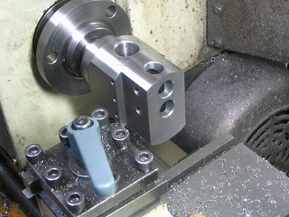
23. Setup for beveling gib plate. Material is mild steel, 3
mm thick. |
 |
24. Lightly machine outer surface, followed by sanding off machining
marks on a belt sander.
Note that the sub-head and head are tightened in an aligned position, and
that the head and arbor are joined by the Jacob's taper.
|
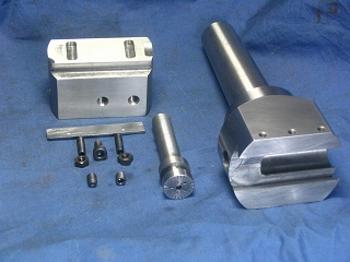 |
25. Boring bar parts. |
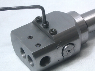 |
26. Use left and right screws to adjust gib tightness. Use center screw
for locking.
Completed !!
|
|
|
 |
|

