 |
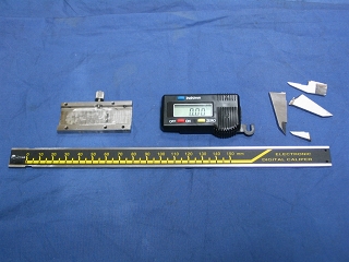
1. Unnecessary parts cut away. Use care NOT to OVERHEAT during
cutting.
|
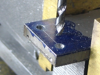 |
2. Drilling two 2 mm holes on end of scale, VERY hard stainless steel.
Carbide bits eventually completed the task, but only after
damaging three bits. |
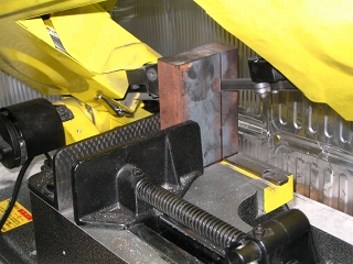 |
3. Rough-cutting base from a block of cast iron. |
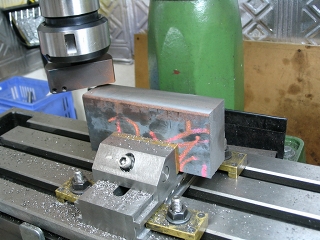 |
4. Fly cutting edge of base.
The fly cutter uses a triangular carbide insert as shown in Article Number
36.
The material is a block of the cast iron. |
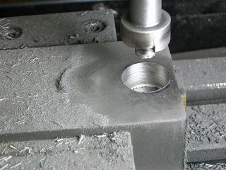 |
5. Counterboring hole in base. |
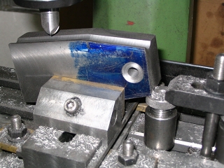 |
6. Grooving base for finger grip, followed by rounding all corners
with a reverse round end-mill.
Base is held in vise, with additional support of jack screw.
|
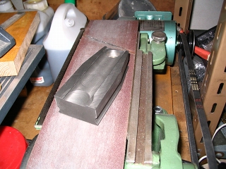 |
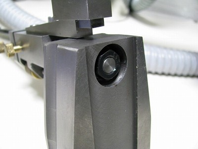
7. Surfaces finished on belt sander after machining.
|
 |
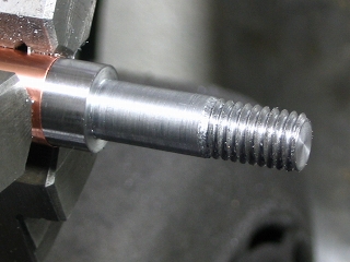
8. Support shaft threaded. The diameter is 12 mm and the material
is hard steel, sometimes called "silver steel" or "drill
rod."
8a. Support shaft attached to base with nut.
|
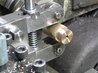 |
9. Knurling fine-adjust nut; brass, 16 mm diameter.
The following procedure was used -
Provide a generous supply of oil.
Clean knurled area after each pass.
Wear eye protection.
Inspect quality with 10 X magnification paying particular attention to
the form of the crests. |
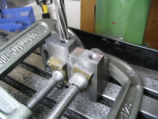 |
10. Reaming slide hole in slide base.
The right-hand piece contains an error, and is used only to aid work-holding.
|
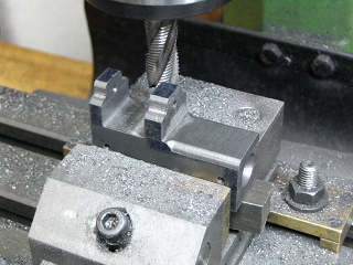 |
11. Machining slide base.
|
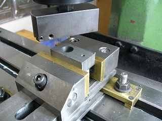 |
12. Fly cutting fine adjusting block. |
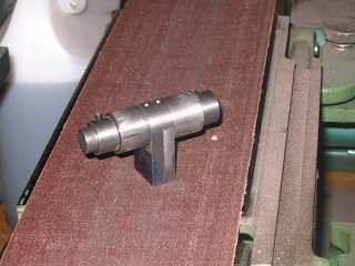 |
13. The two fixed supports of the scale are rounded on the belt sander
with the aid of a dedicated tool; a hardened collar on each side of the
fixed supports is used as a guide.
|
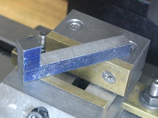 |
14. The angle bar for foot has been rough cut. Material is
mild steel. |
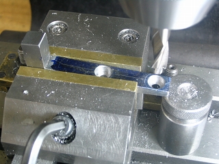 |
15. Drilling two mounting holes.
They are countersunk for the screw heads. |
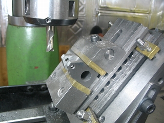 |
16. The slide base was reshaped to a more pleasing profile. (Photo
#11 shows the original profile.) |
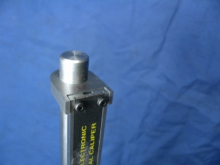 |
17. Attaching scale to top bracket with 2 mm screws. |
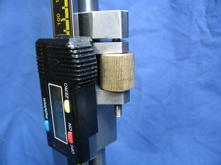 |
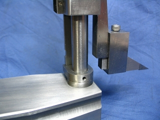
18. Fine adjustment mechanism. |
 |
19. Foot attached to the lower end of the angle bar with box bracket. |
|
|
|
|
 |
|
