 |
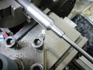
Machining one of the three adjusting screws, one end of which is held in
the chuck, the other supported by a live center (Out of the frame.) |
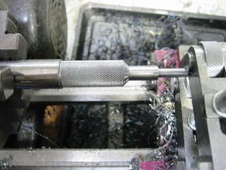 |
Adjusting screw knurling complete. |
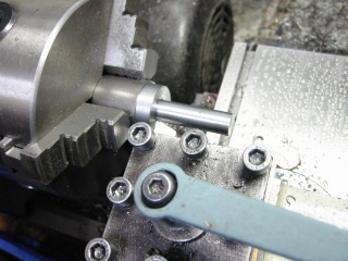 |
Making one of three locking screws that holds the fingers is place. The
head size is 22 mm and the diameter is 10 mm. |
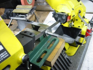 |
One of the locking screws is "parted off" on the bandsaw,
much easier than on the lathe. Extra material is left for facing.
|
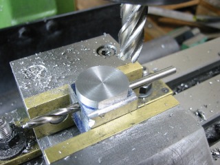 |
The locking screws are held in a dedicated fixture for machining two parallel
flats.
|
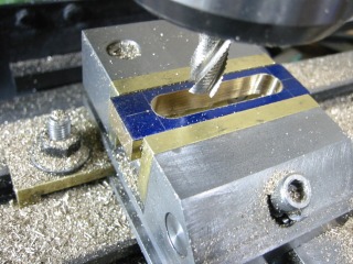 |
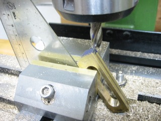
Slotting a brass finger, one of three. An easy step. |
 |
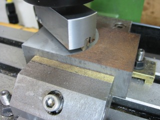
Setting up to machine the finger nose bevel. |
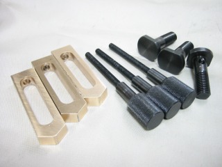 |
The fingers, adjusting and locking screws.
(Visitors to your site may be interested in knowing how you blackened the
screws. A nice touch, I might add. I don't know, so could not inform
them.)
|
 |
Machining base #1.
Note - The base assembly consists of base #1 and #2, bolted into an "L"
shape.
|
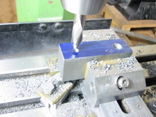 |
Machining base #2. |
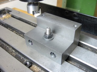 |
Base #1 and #2 bolted together. Top surface being milled.
|
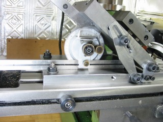 |
Preparing to machine a female vee to match the lathe
v-way.
A protractor was used to precisely set the tilting angle plate.
See Article Number 30 for details on making a tilted angle plate. |
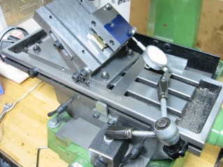 |
Aligning base with dial indicator.
|
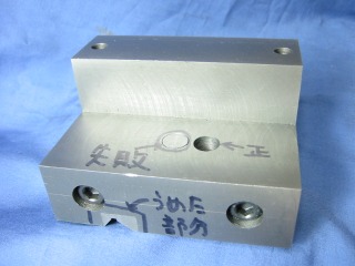 |
The base completed, including vee to mate with lathe.
|
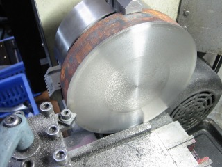 |
Facing the support frame, diameter 140 mm , material cast iron.
|
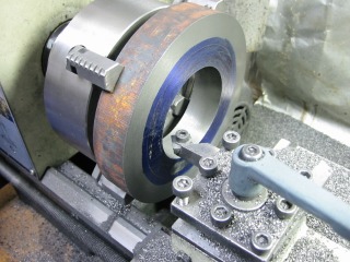 |
Boring center hole to size. |
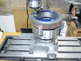 |
Drilling three equidistant holes in the support frame. The support
frame is held in the lathe chuck, mounted on the Index Table. See
Article Number 23 for the design of the Index Table. |
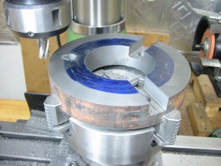 |
Machining three channels with a 12mm end mill.
The channel width is 18mm.
|
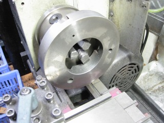 |
Turning the outside edge of the support frame. |
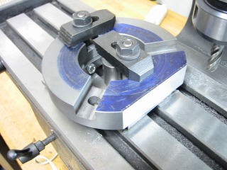 |
Machining a face on support frame for mounting base. |
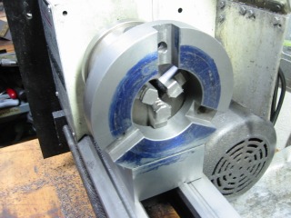 |
Verifying center height of steady. |
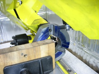 |
Radial sectioning of support frame. The bandsaw cuts were cleaned
up on the mill. |
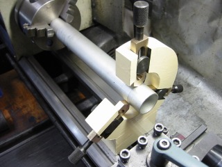 |
Completed!
I have painted the steady a similar colour to the lathe . |
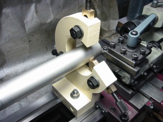 |
The rear view of the steady. |
|
|
|
|
 |
|
