 |
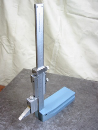
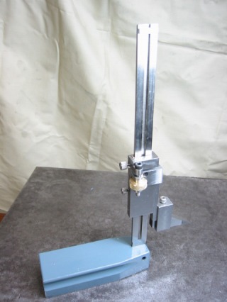
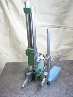
Two height gauges are shown -- a commercial unit
on the left and the gauge I made on the right.
The compact gauge offers greatly improved handling.
|
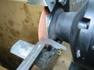 |
Cutting off caliper jaw using bench grinder with narrow wheel.
|
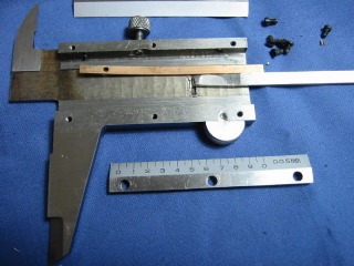 |
This is the vernier caliper disassembled .
--------
Disassembled vernier caliper. |
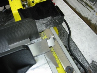 |
The base of the jaw being cut on the bandsaw. This part hasn't
been hardened. |
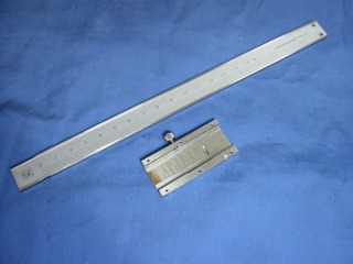 |
The two main parts remaining after trimming. |
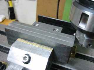 |
Fly cutting cast iron base.
See Article Number 36 for information on making a fly cutter.
See Article Number 29 for information on making a vise.
|
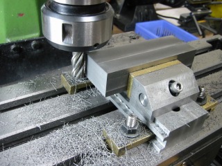 |
Machining the end of the base. |
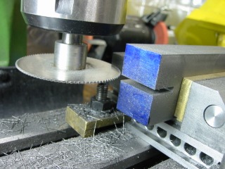 |
Slotting the base, 3.2 mm or sized to fit the scale.
See Article Number 44 on making a metal saw holder. |
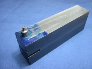 |
Fixing a mistake.
A miss-drilled hole was filled with a rod held in place with high strength
Loctite 2760 or equivalent. |
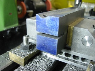 |
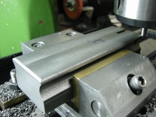
Machining the half-round finger groove to aid holding and moving the gauge.
The round cutter was shop made as shown in Article Number 34. |
 |
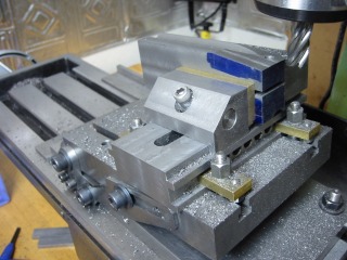
A large chamfer is added to top edges of the base for hand comfort. |
 |
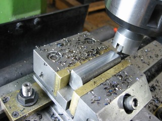
Machining tapers on front edges of base.
The base is held in a vise, resting on a tilting table, raised to a slight
angle.
See Article Number 30 for making a tilting table.
|
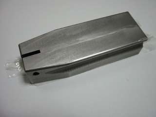 |
Base machining is finished. |
 |
Machining the scriber foot from a round bar of SKS3 steel. (Similar to
1095 carbon tool steel.)
|
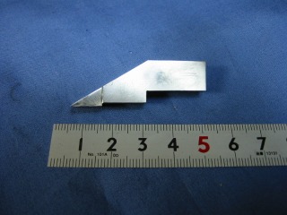 |
Scribing foot finished and ready for heat treating. |
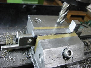 |
Machining the scriber post angle bracket. |
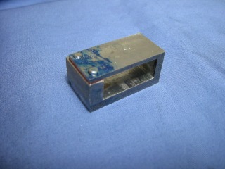 |
This is the box bracket that joins the scriber foot
to the scriber post angle bracket.
|
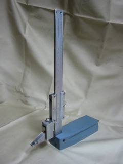 |
At this point most of the work has been done and the height gauge
can be used even though the micro-adjustment mechanism hasn't been
installed. |
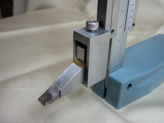 |
Zeroing the scriber foot by placing metal shims between the foot
and post angle bracket. |
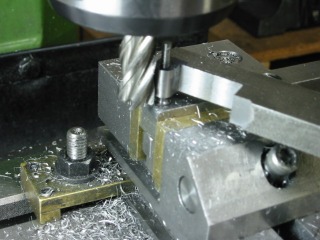 |
Machining the micro-adjustment mechanism frame. |
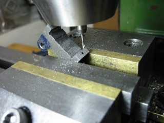 |
Machining micro-adjustment frame with a 1.6 mm end mill.
|
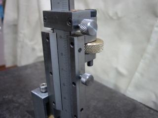 |
Micro-adjustment mechanism installed. |
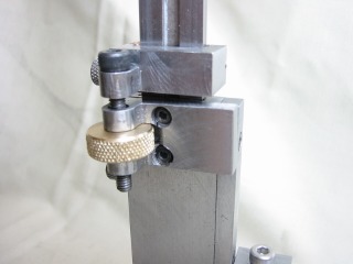 |
Close-up of micro-adjustment mechanism. |
|
|
|
|
 |
|
