 |
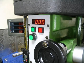
1. A motor control panel is mounted up front to be within
easy reach. This panel includes ON and OFF switches, speed control, and
a display of the variable frequency voltage supplied to the motor -- proportional
to spindle RPM.
|
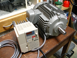 |
2. Bench testing the new motor and motor controller. The motor is a HITACH, model EFOUP1.5KW, and the motor controller is Yasukawa, model VS mini V7 200V 1.5Kw. |
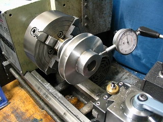 |
3. Original equipment pulley being set up for for increasing bore
size from 22 mm to 24 mm to accommodate the larger shaft of the new motor.
|
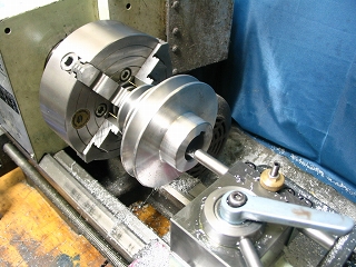 |
4. Boring to fit 24 mm shaft. The pulley material is aluminum .
|
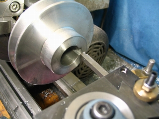 |
5. Keyway being deepened after increasing the bore size. A succession of shallow cuts were made by moving the carriage.
Note - It was not possible to use the dedicated Keyway Cutting Tool shown
in Article Number 41 because it did not have adequate stroke length. |
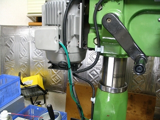 |
6. New motor installed and wired to the motor controller. The fan
runs at full speed whenever the milling machine motor is powered. |
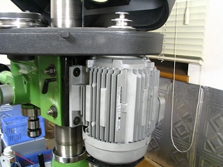 |
7. Another view of the new motor.
|
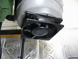 |
8. An external fan was added to boost the cooling air of the motor's fan, especially when the motor is operated at low speed. |
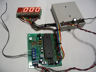 |
9. The main components of the speed controller and display are shown.
The speed indicator display was originally part of the main body, but this
presented mounting problems... it was too big to fit into the milling machine
recess. The display was separated from the main body and extension
wiring added.
|
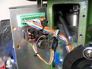 |
10. The inner view of the control panel. |
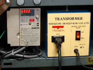 |
11. The motor controller, on the left, is powered by a step-up transformer.
The motor controller supplies variable frequency power to the
motor under control of the operator. |
 |
|