LATHE

Selection of the Model


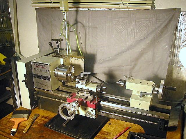
My lathe is 8x18,  weighs 80Kg (176 pounds) and is three times heavier than the lathe I initially planned to buy. This is my only lathe  and I have become very familiar with it since its purchase  in 1997. The original motor was rated at 400 watts, but has been upgraded to 750 watts.

My lathe was purchased while I was living in Europe during the 1995-1999 years and European readers may recognize the "Optimum" name which is well known in Europe. 

Installation

The lathe is positioned on a wooden bench, loosely  bolted in place.  I found that firm bolting caused the bed to distort. 

In an effort to firmly bolt the lathe to the bench top, I tried the adjustment procedure described in the "The Amateur's Workshop" book, but I was not successful.  I am not sure why, but perhaps the workbench surface was not flat or level enough. 

Specification

Capability and Accuracy

This lathe has the capacity to turn brass or aluminum to a depth of 3 mm at 1,000 rpm, and turn steel to a depth of 1 mm.

The spindle runout is less than 2/100 mm (0.02 mm), a value within the JIS, Japan Industry Standards.

Shop-made Lathe Accessories  

The following is a list of articles found on my website that describe accessories that I have made for extending the capability of my lathe.  

 2.  DIE HOLDER  
 4.  KNURLING  HOLDER 
 8.  FILING REST

 9.  TOOL HOLDER 

10. SUDS  SYSTEM 
13. MANUAL SPINDLE  HANDLE 
20. CARRIAGE STOP  
25. CHUCK KEYS

26. FOUR JAW CHUCK FLANGE 
37. FIXED STEADY
38. BORING BAR HOLDER
41. KEYWAY CUTTING TOOL 
43. LARGE DIAMETER LATHE DOG 
49 QUICK CHANGE  TOOL POST 
50. KNURLING HOLDER
52. QCTP INSERT TOOLHOLDERS AND TOOLHOLDER FOR QCTP
55. BACK PLATE 

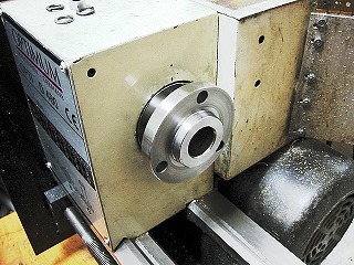
1. The spindle has a MT3 taper and  a 20 mm through-hole.

The surface of the flange has been very  slightly turned to better true it.

.

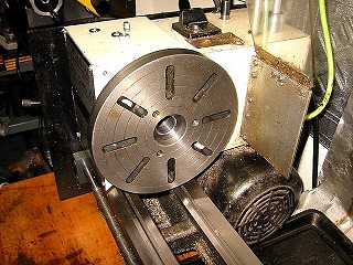
2. Face plate attached. It appears to be a versatile accessory, but it has yet to be used.

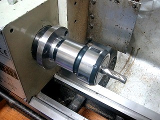
3. Collet holder attached with drawbar.

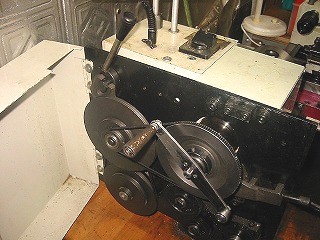
4. The handle (top, left with black handle)  is for changing the belt position. 

The motor switch -- seen on the panel -- provides for reversing the direction of rotation.

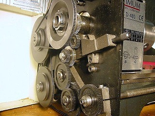
5. The lever (foreground) controls  leadscrew drive : FWD/NEUTRAL/REV

The original gears were plastic and have been replaced with  purchased metal gears.  Keyways were cut in the new gears using the keyway cutter shown in Article Number 41.  

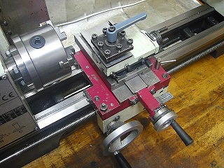
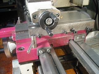
6. Cross-slide and top-slide, with 4-way tool post mounted atop.  
7. Way-wipers on carriage. The wiper material is soft cushion rubber.


8. View from the tailstock. 

The lever on the carriage was added for convenient locking of the carriage. 

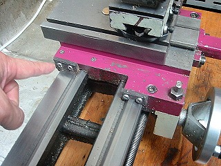
The screws for gib adjustment have been changed to cap screws, allowing for use of a larger wrench. 

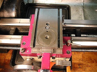
A cross slide table without top slide.

The with of the T-Slot is 7mm.

-----

9. Cross-slide table without top slide. 

T-slot width is 7 mm.

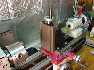
10. Vertical milling attachment installed on cross-slide.  

Milling was accomplished using this arrangement until I purchased a milling machine.


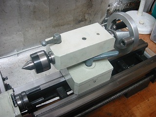
11. Tailstock with MT2, live center installed. 

A balance weight was added to the tailstock handwheel.  

The  tailstock wrench is the same as used for the 4-way toolpost.

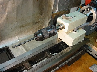
12. Keyless chuck, with MT2  shank, installed in tailstock taper.
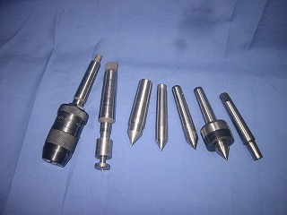
13. An assortment of tailstock and spindle accessories.

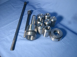
14. Collets,  collet-holder, and drawbars.  (The longer drawbar is used on the mill.)