METAL-SAW HOLDER
After prolonged use my metal saw became worn and needed replacement. The
new blade has 72 teeth, a diameter of 70 mm, and a hole
size of 24.5 mm, different from my old saw.
A new holder was made to match the bigger hole size. Its design
follows the design of the saw arbor described in Article Number 17.
|
 |
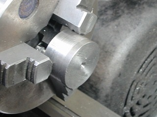 |
1. Machining the CAP from free-cutting steel, diameter 30 mm.
NOTE
See 7.5, below for an exploded view and the names of the individual
parts.
|
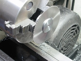 |
2. Using saw to check fit . A neat fit with no play is
ideal. |
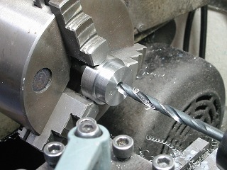 |
3. Drilling 6.2 mm hole in CAP.
|
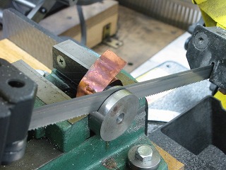 |
4. Trimming CAP while copper foil protects machined surface.
|
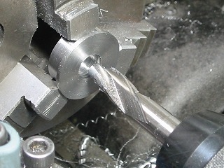 |
5. Counterboring CAP for head of locking screw.
|
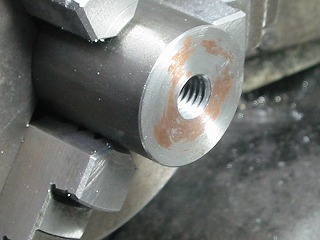 |
6. The BODY (SHAFT side) has been drilled and tapped to match threads of
shaft.
The material is free-cutting steel, diameter 30 mm.
|
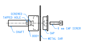 |
6.5
Exploded view of arbor. |
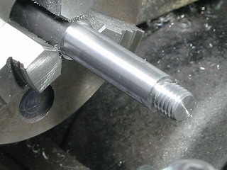 |
7. Machining SHAFT from free-cutting steel. Blank size
of 14 mm is turned to 12 mm and threaded to mate with the BODY.
|
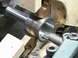 |
8. The BODY is threaded onto the SHAFT and locked with high strength adhesive
such as Loctite 2760.
A fixed steady supports the BODY during boring.
See Article Number 37 for more on the Fixed Steady.
|
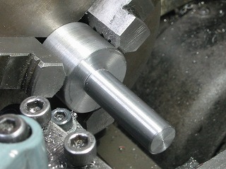 |
9. After machining BODY, cut off excess and face end of SHAFT. |
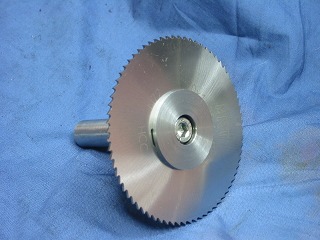 |
10. Completed. |
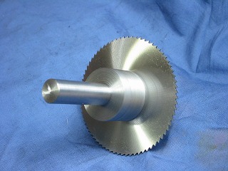 |
11. Back view of the holder. |
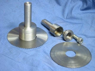 |
12. The new one is on the left and the old one on the right.
|
|
|
 |
|