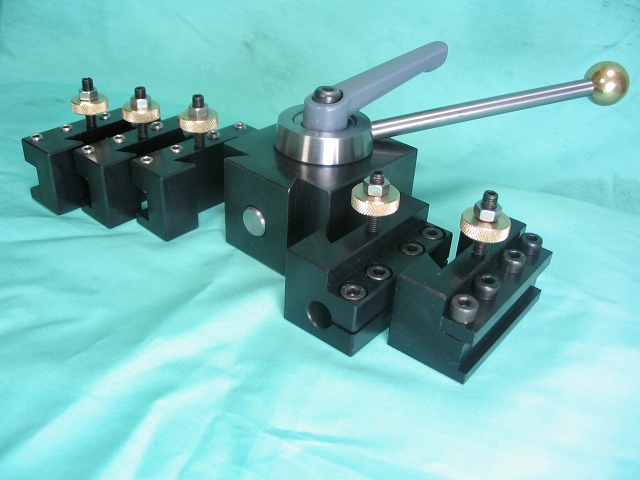
QUICK CHANGE TOOL POST My lathe came with a four-way tool post and I wanted to convert to a "quick change" system. Quick change systems are commercially available, but I decided to make my own, modeled after commercial designs. Quick change system consists of a Quick Change Tool Post, QCTP and Quick Chance Tool Holders, QCTHs. Commonly, a number of QCTHs are dedicated to hold a particular bit. Any QCTH can be mounted on the QCTP. The below photographs start with a making of a variety of Quick Change Tool Holders, followed by the making of a Quick Change Tool Post. Design goals - The QCTP shall easily replace the four-way tool post. A wide range of cutting tools shall be accommodated, including parting tools and boring bars. The design shall be robust and secure. Once set up, no adjustments shall be required. |
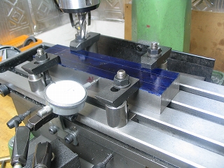
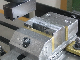
1. (HOLDER) Mild steel section, 30 mm x 60 mm x 250 mm being aligned. As shown below, the entire length will be slotted and dovetailed, and then cut to length to make individual tool holders, QCTHs. |
|
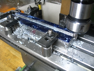
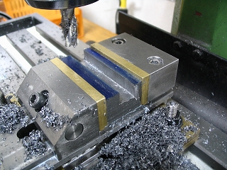
2. (HOLDER) Slotting 8.5 mm deep, using 12 mm roughing end mill at 340 rpm. Slotting time about 12 minutes. |
|
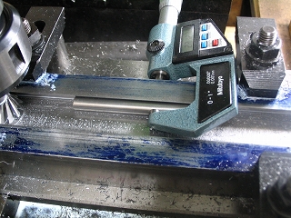
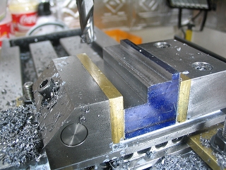
3. (HOLDER) Checking dovetail with digital micrometer. |
|
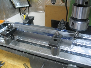
4.(HOLDER) Chamfering dovetail corners after machining. The length is then cut into individual "holders," with allowance for milling. |
|
5. (HOLDER) Fly cutting a typical holder 30 mm section. . See Article Number 36 for making a fly cutter. See Article Number 29 for making a precision milling vise. |
|
6. (HOLDER) Cutting tool groove in holder using a roughing end mill. |
|
7. (HOLDER) Making a parting tool holder. |
|
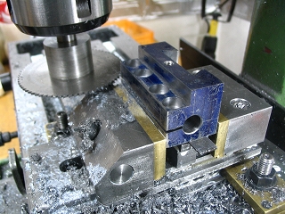
8. (HOLDER) This is for the boring bar. ------ 8. Slitting a boring bar holder, one of many QCTHs that were made for the QCTP. |
|
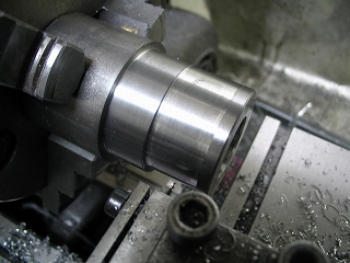
9. (ECCENTRIC CAMj Making the Quick Change Tool Post starts with making the eccentric cam. The material is free-cutting steel, 40 mm diameter. |
|
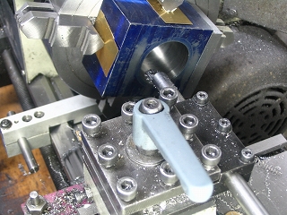
10. (BODY) Boring the body while held in 4-jaw chuck with protective strips. |
|
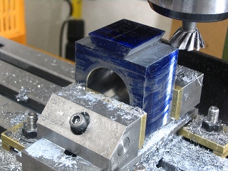
11. (BODY) Cutting the body's dovetails for a neat fit with the dovetails of the tool holders, QCTHs. |
|
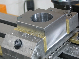
12. (BODY) Chamfering body edges with deburring tool. After deburring, remove machining marks with a belt sander. |
|
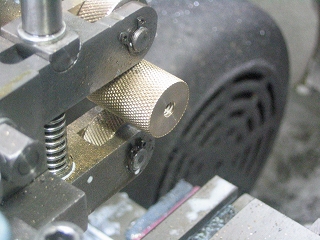
13. (SUNDRY PARTS) Knurling brass rod to make height adjustment nuts, one for each tool holder. Several made at one time. |
|
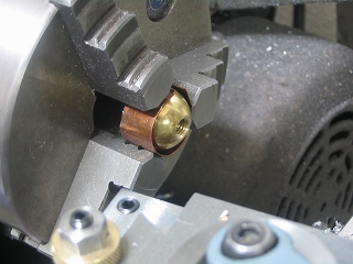
14. (SUNDRY PARTS) Machining ball for end of the lock lever. Material is brass. |
|
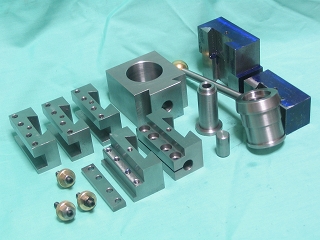
‚P‚TD Parts for QCTP and QCTHs prior to black oxide finishing. |
|
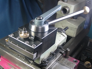
16. QCTH mounted on QCTP, ready for use. Locking is smooth and easy, and overall I am very pleased . |
|