 |
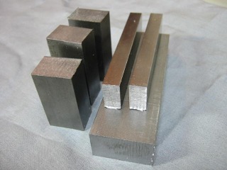
The raw material -- mild steel -- is assembled. |
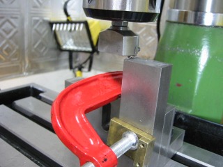 |
Machining the base with a fly cutter. See Article Number 36
for more information on the fly cutter. |
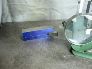 |
Marking the base, followed by careful checking to avoid blunders.
|
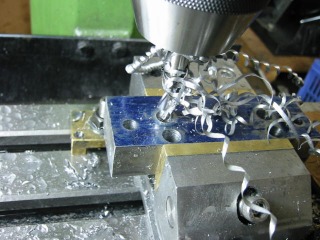 |
Counter-boring using a step-drill bit and plenty of cutting oil.
The heads of the screws used to secure the side posts
to the base fit into the counter-bores.
|
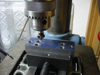 |
All holes of the base are slightly chamfered. |
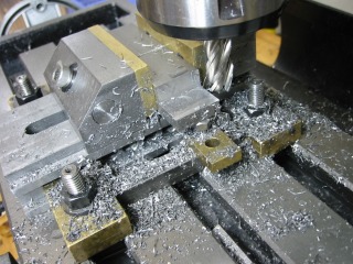 |
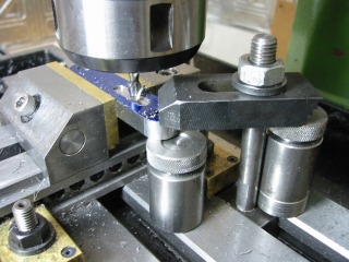
One of the two side posts being milled. The workpiece was accurately
positioned and clamped in the vise.
|
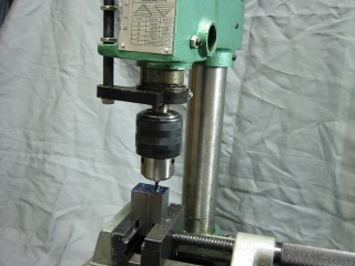 |
Tapping was done using my tapping stand. See Article Number 12.
Although I am well equipped to do tapping, it is not one of my favorite
activities. |
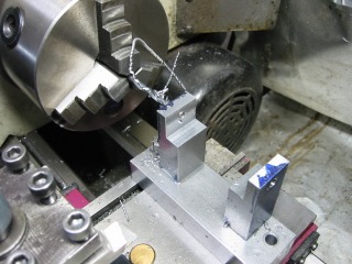 |
The side posts are fastened to the base and the based is fastened to the
t-slots of the lathe.
At this point, alignment is verified to assure that the centers of
the side posts lie on the lathe spindle axis. |
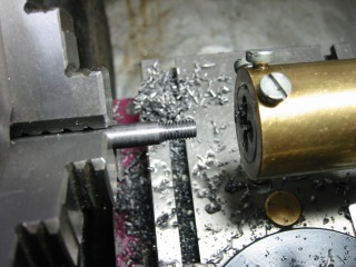 |
A pivot shaft being threaded. The material is free-cutting steel.
See Article Number 2 for information on the Die Holder design.
|
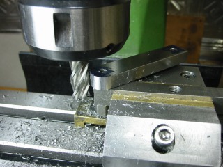 |
Rounding the swinging arms.
Rounding is accomplished by manually rotating the arm while it is pivoted
on a pin. |
 |
Slotting the swing arm with 6 mm end mill. See Article Number 24
for more information on Jack Screws. |
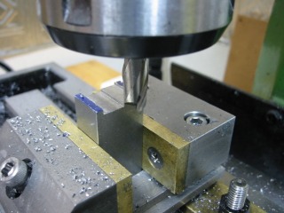 |
A shallow channel is machined on one side of the tool-holder block, followed
by machining an identical channel on the other end. |
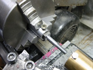 |
Making a pivot screw, one of two required. The screws were made from
square bar, held in a fixture in the three-jaw chuck. The material
is free-cutting steel. |
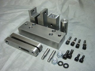 |
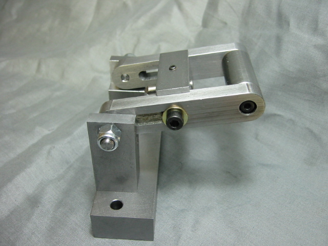
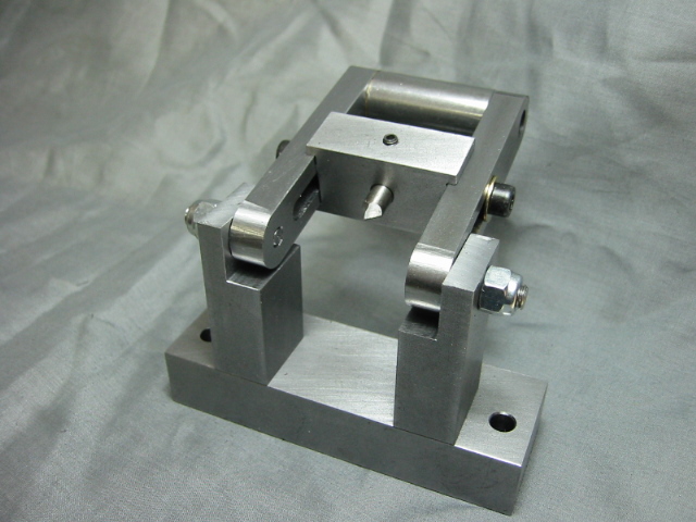
All parts have been made, a very enjoyable moment. |
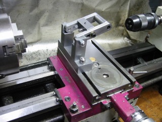 |
Tool mounted on lathe, with cross-slide positioned to center the tool bit
onto the lathe spindle axis.
|
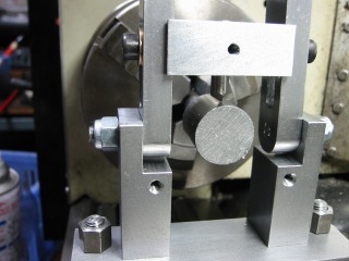 |
The starting position is shown for making a ball. The tool bit is
located on the lathe spindle axis, and the tool slide has been adjusted
to set the depth of cut. |
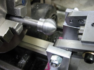 |
Testing has been successful. |
 |
|
