TILTING ANGLE TABLE

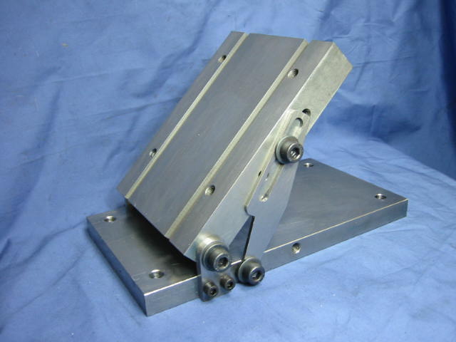
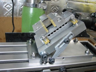
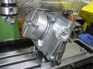
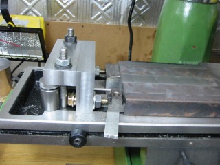
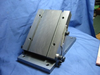
This article  shows the making of a tilting angle table which can hold a vise or rotary table. Also, a workpiece may be directly mounted on it.  The table can be fixed firmly at any angle within its  range of 0 to 90 degrees.  

The top plate is cast iron, 125 mm wide, 160 mm long, and 25 thick.  

The base plate is mild steel, 125  mm wide and 225 mm long, and 16 mm thick.   

The total weight is 6.8 Kg.

As show below the top plate has two t-slots, sized the same as  my lathe cross-slide, so all of the accessories are interchangeable. The four threaded holes in the top plate are used to mount an Index Table or Vise.  

See Article Number 23 for details on the Index Table and Article Number 29 for details on the Vise.

  <<Figure is here>>

Making of Tilting Angle Table
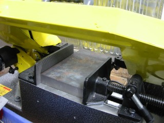
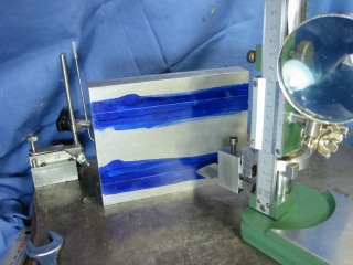
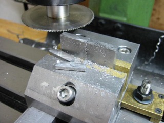
Cast iron, 25 mm thick, being sawed to make the  top plate.
I big vise would have been ideal for holding the base plate, but I don't have one and had to improvise.

Holding the work as shown in the previous photograph was not as stable as it could be. 

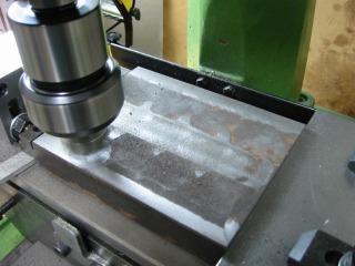
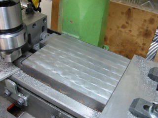
The plate is surfaced  using a cutting depth of 0.25 mm.

The plate has surfaced with a small-diameter fly cutter.

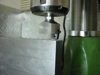
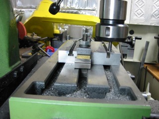
Surfacing with a fly cutter.

A carbide insert is held in the fly cutter with a set-screw.  See Article Number 21 for fly cutter details.
Marking t-slot locations on top plate after it was trued and surfaced.
Milling t-slots in top plate using  dimensions matching  those of my lathe cross-slide. 

Cutting cast iron produces a messy, fine grained powder.

Article Number 18 shows the making of a t-slot cutter.

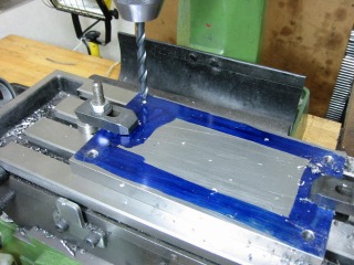
Drilling  holes in the base plate for fastening it to the mill table with t-nuts.  The base plate  thickness is 16 mm.

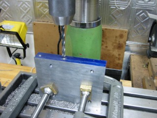
Drilling holes in side of the top plate prior to tapping to 8 mm.   

WARNING - The depth of drill should not reach t-slot. 

Sawing the pivot  plate, one of two. 

Thickness is 6 mm.  Half-rounding is done by hand.


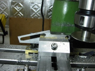
This is the setup for cutting the angle holding plate, two required.

The sliding slot must be cut before this procedure.
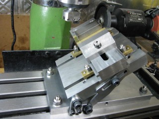
All the parts have been assembled. 
A typical application of the Tilting Angle Table is shown.