|
|||||||
| << Drawing is here >> | |||||||
 |
|||||||
 |
|||||||
 |
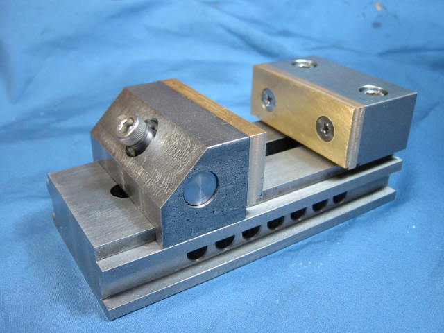
Mild steel is used throughout, except for the brass inserts. |
||||||
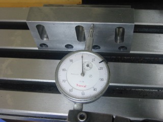 |
Accurately aligning the angle plate on the mill table. See Article Number 28 for additional information on the angle plate. |
||||||
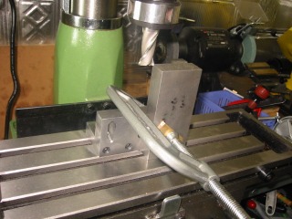 |
Precisely squaring the body edges. A precision trysquare was used to set the right angle. Fine adjustments were made with taps of a small hammer After milling, the workpiece was checked to assure that it did not shift during machining. |
||||||
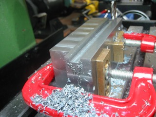 |
Cutting the first side guide slot. The overall width is 10 mm and the depth 15 mm. Cuts progressed in 0.5 mm steps using a roughing end mill. After completing the first slot, turn the workpiece over without changing the setup to retain symmetry. Second slot cuts also progressed in 0.5 mm steps. |
||||||
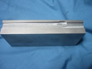 |
Unfortunately, a locking screw of the mill loosened and led to running off track. The ruined piece was saved for another project and a new piece was selected for a fresh start. |
||||||
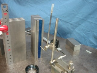 |
Marking out the side holes after machining the two guide slots. |
||||||
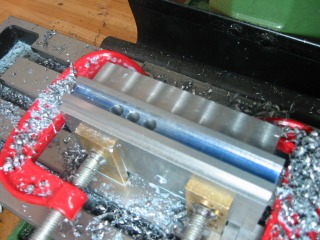 |
Drilling the holes, 50 mm deep -- a key process in making this vise calling for precise drilling -- the holes must be straight and positioned accurately. The hole positions were indexed using a dial indicator. The marking out lines served for double-checking to avoid careless errors. |
||||||
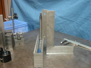 |
The holes were drilled to 7.8 mm and reamed to 8 mm. Since hole accuracy is critical for smooth operation of this vise, each hole was inspected using a mandrel and trysquare. All holes passed. |
||||||
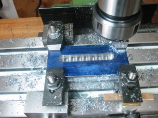 |
Cutting the slot in the underside of the base. The slot depth extends to the centerline of the cross-drilled holes. The end mill 12 mm. |
||||||
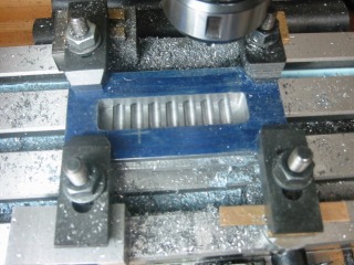 |
Completion of the underside slot cutting. |
||||||
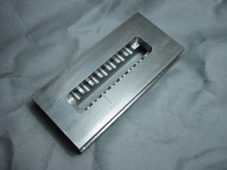 |
A slot has been cut through from the underside of the base. A 12 mm end mill was used, with depth increments of 0.5 mm. |
||||||
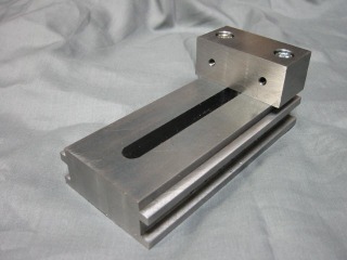 |
Initially the fixed jaw was mounted with robust machine screws set
into counterbored holes.
Eventually two tight-fitting dowels were added to fix the jaw and provide additional rigidity. The dowels were set with Loctite, high strength. |
||||||
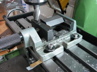 |
Machining the moving jaw while held in a drill press vise. The drill press's lack of precision makes it difficult to machine parallel surfaces on the mill. As shown, shims were added as packing under the vise. |
||||||
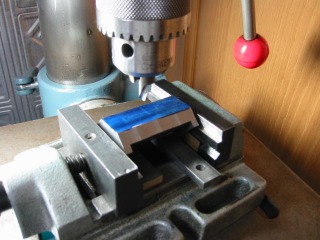 |
Drilling the hole for the vise's tightening screw, starting with a center-drill. |
||||||
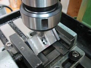 |
Machining slot for tightening screw. |
||||||
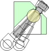 |
The clearance space in the moving jaw is made as shown in the figure. The white area is the clearance space. |
||||||
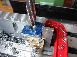 |
Reaming the cross-hole in the moving jaw to a diameter of 12 mm. |
||||||
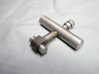 |
This is the tightening system. |
||||||
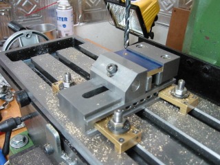 |
Drilling a brass jaw plate while held in partially finished vise. |
||||||
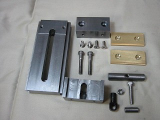 |
All the finished parts. |
||||||
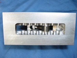 |
View of the underside of the vise. |
||||||
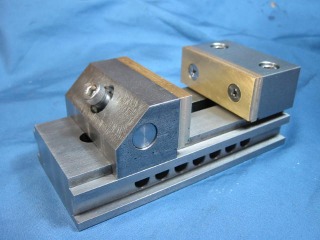 |
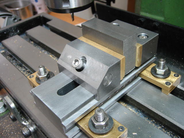
It is complete. The jaw plates are made of brass. |
||||||